Case story
Mirafi® SR - XinFeng Landfill Expansion
China, Guang Zhou
Project Data
| Project | Reinforced Containment Bund for Landfill Capacity Expansion |
| Location | GuangZhou, China |
| Contractor | Guangdong Foundation Engineering Group Co., Ltd. |
| Products used | Mirafi® SR |
Background
Guangzhou is the third largest city in China, behind Beijing and Shanghai. With more than 10 million residents, Guangzhou is one of China’s leading manufacturing and commercial centres and generates significant amount of MSW. For many years Guangzhou’s solid waste has mostly been sent to the Xinfeng MSW Landfill for disposal. Xinfeng Landfill is located at the foot of Maofeng Mountain in a valley to the south of Xinfeng Village, Taihe Town in Baiyun District of Guangzhou City. Xingfeng Landfill is about 38 kilometers away from Guangzhou city centre (see Figure 1). It covers an area of 917,000 m2, out of which is 565,000 m2 of landfill cell area with a landfill capacity of more than 26 million m3. It is the second largest landfill in China in terms of capacity and daily MSW intake, just behind Laogang MSW Landfill in Shanghai. The landfill was originally developed in 2003 with a design capacity of 19.3 million m3 and based on 3,000 tonnes of MSW daily had a projected collection life of 20 years. By 2010 Guangzhou was producing 8,000 tonnes of MSW daily, out of which 7,000 tonnes were sent to Xinfeng Landfill. Today, Xinfeng Landfill still handles on the average 75% of the daily MSW generated in Guangzhou.
The liner for Xinfeng Landfill is basically a double geomembrane system with a 1.5 mm thick high density polyethylene (HDPE) geomembrane as the primary liner and a 1 mm thick HDPE geomembrane as the secondary liner. Above the primary liner is a leachate drainage layer consisting of continuous aggregate blanket with in-laid perforated drainage pipes to drain away the generated leachate. A filter geotextile separates the aggregates and the solid waste placed in the landfill. In-between the primary and secondary liners is a leachate detection layer consisting of continuous aggregate blanket with in-laid perforated drainage pipes to drain away any leachate leaking through the primary liner. Cushion geotextiles are placed between liners and aggregates to protect the liners from aggregate punctures. Xinfeng Landfill also has an on-site leachate treatment plant and a methane recovery system for energy.
Geology and Site Terrain
The geology of area consists generally of Quaternary Alluvium overlying various stages of in-situ weathered granite. The landfill site was constructed on hilly ground which is generally higher in the north. Two river valleys, separated by a central ridge, cut across the site in an approximately N-S direction. The elevation of valley bottom ranges in general from Reduced Level (RL) 120 m in the north to RL 70 m in the south, with surrounding hills ranging from RL 185 m to RL 130 m. The thickness of the completely weathered granite layer is about 1.5 to 6 m. The overlying alluvium is brownish red sandy clay with thickness ranging from 1 to 11.5 m. Groundwater is typically found between 1 to 6 m below ground level. The outlet of a stream which flows from the site is 700 m upstream from the inlet to Jinkeng Reservoir, making leachate control a major design concern for Xinfeng Landfill.
New Reinforced Soil Containment Bund to Increase Landfill Capacity
By 2012 it was clear that Xinfeng Landfill was quickly running out of capacity. There was an urgent need to find a way to increase the capacity of Xinfeng Landfill, without which Xinfeng Landfill would have to stop accepting waste. This would have drastic consequences for the city of Guangzhou as new landfill and incinerator projects are still at a planning stage. The decision was made to construct a 37 m high and over 300 m long containment bund. The new containment bund will contribute 7.5 million m3 of capacity increase (see Figure 2). This new containment bund is located between the existing leachate treatment plant and the existing low containment bund at the southern end of the landfill. Figures 3 and 4 show the layout plan and the typical cross-section of the reinforced soil containment bund respectively.
Due to site constraints and in order to gain optimum landfill capacity increase, the sides of the new containment bund were designed to slope angle of about 45o. Reinforced soil technology was adopted for the design of the new containment bund. A row of 1.6 m diameter bored piles was designed to act as shear key at the toe of the new containment bund to provide adequate stability against global failure. The bored piles typically ranged from 18 to 21 m in length. The new containment bund has a maximum height of 37 m, 2 m of which is embedded below ground level. There are 3 intermediate berm setbacks of 2 m each; at RL 95 m, RL 105 m and RL 115 m. The top of containment bund is 12 m wide at RL 125 m. Reinforcements are placed at 0.5 m vertical spacing and are continuously placed over the entire backfill and wrapped around soil bags at both ends. Subsoil drainage blankets are detailed at the lowest level of containment bund and at every berm setback level. The new containment bund is connected into the original containment bund using steel dowels. Two different grades of geotextile reinforcement are used; Mirafi® SR5000 with ultimate tensile strength of 500 kN/m below RL 105 m and Mirafi® SR2500 with ultimate tensile strength of 250 kN/m at and above RL 105 m. When completed, a layer of topsoil will be placed over the external face and vegetated over.
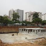
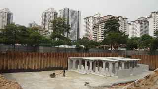
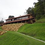
Construction of New Reinforced Soil Containment Bund
Construction for the new containment bund started in April of 2016. The first roll of reinforcement geotextile was laid on 15th April. Figure 5(a) shows the overall view of the containment bund construction. Figure 5(b) shows the close up of the reinforcement geotextile wrapping around soil bags at the facing area. By the end of August the new containment bund had reached RL 120 m which was sufficiently high enough to allow the liner system extension works behind the new containment bund to begin and be connected to the original liner system. This was an important milestone as the liner system extension has to be initiated before waste placement can proceed. Figure 5(c) shows the liner system extension behind the new containment bund. Figure 5(d) shows the significantly completed containment bund with top soil placed over the outer face.
?w=150&h=150&action=crop)
?w=320&h=180&action=crop)